Holography dates from
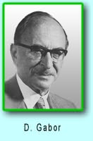
1947, when British (native of Hungary) scientist
Dennis Gabor developed the theory of holography while working to improve the resolution of an electron microscope.Gabor coined the term hologram from the Greek words holos, meaning "whole," and gramma, meaning "message". Further development in the field was stymied during the next decade because light sources available at the time were not truly "coherent" (monochromatic or one-color, from a single point, and of a single wavelength).
This barrier was overcome in
1960 by Russian scientists
N. Bassov and
A. Prokhorov and American scientist
Charles Towns with the invention of the laser, whose pure, intense light was ideal for making holograms.
In that year the pulsed-ruby laser was developed by Dr.
T.H. Maimam. This laser system
(unlike the continuous wave laser normally used in holography) emits a very powerful burst of light that lasts only a few nanoseconds (a billionth of a second). It effectively freezes movement and makes it possible to produce holograms of high-speed events, such as a bullet in flight, and of living subjects. The first hologram of a person was made in
1967, paving the way for a specialized application of holography: pulsed holographic portraiture.
In
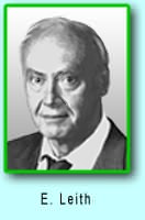
1962 Emmett Leith and Juris Upatnieks of the University of Michigan recognized from their work in side-reading radar that holography could be used as a 3-D visual medium. In 1962 they read Gabor's paper and "simply out of curiosity" decided to duplicate Gabor's technique using the laser and an
"off-axis" technique borrowed from their work in the development of side-reading radar. The result was the first laser transmission
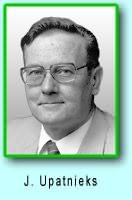
hologram of 3-D objects (a toy train and bird). These transmission holograms produced images with clarity and realistic depth but required laser light to view the holographic image.
Their pioneering work led to standardization of the equipment used to make holograms. Today, thousands of laboratories and studios possess the necessary equipment: a continuous wave laser, optical devices (lens, mirrors and beam splitters) for directing laser light, a film holder and an isolation table on which exposures are made. Stability is absolutely essential because movement as small as a quarter wave- length of light during exposures of a few minutes or even seconds can completely spoil a hologram. The basic off-axis technique that Leith and Upatnieks developed is still the staple of holographic methodology.
Also in
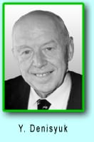
1962 Dr.
Yuri N. Denisyuk from Russia combined holography with 1908 Nobel Laureate Gabriel Lippmann's work in natural color photography.
Denisyuk's approach produced a white-light reflection hologram which, for the first time, could be viewed in light from an ordinary incandescent light bulb.
Another major advance in display holography occurred in
1968 when Dr.
Stephen A. Benton invented white-light transmission holography while researching holographic television at Polaroid Research Laboratories. This type of hologram can be viewed in ordinary white light creating a "rainbow" image from the seven colors which make up white light. The depth and brilliance of the image and its rainbow spectrum soon attracted artists who adapted this technique to their work and brought holography further into public awareness.
Benton's invention is particularly significant because it made possible mass production of holograms using an embossing technique. These holograms are "printed" by stamping the interference pattern onto plastic. The resulting hologram can be duplicated millions of times
for a few cents apiece. Consequently, embossed holograms are now being used by the publishing, advertising, and banking industries.
In 1972 Lloyd Cross developed the integral hologram by combining white-light transmission holography with conventional cinematography to produce moving 3-dimensional images. Sequential frames of 2-D motion-picture footage of a rotating subject are recorded on holographic film. When viewed, the composite images are synthesized by the human brain as a 3-D image.
In 70's Victor Komar and his colleagues at the All-Union Cinema and Photographic Research Institute (NIFKI) in Russia, developed a prototype for a projected holographic movie. Images were recorded with a pulsed holographic camera. The developed film was projected onto a holographic screen that focused the dimensional image out to several points in the audience.
Holographic artists have greatly increased their technical knowledge of the discipline and now contribute to the technology as well as the creative process. The art form has become international, with major exhibitions being held throughout the world.
 observatory mission")