Saturday, September 5, 2015

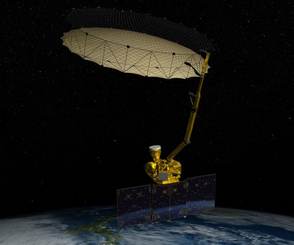
NASA’s Soil Moisture Active Passive (SMAP) observatory mission

Image: NASA’s Soil Moisture Active Passive (SMAP) observatory mission
NASA’s Soil Moisture Active Passive (SMAP) observatory mission, launched in January. A key instrument on the satellite has failed, reducing scientists' ability to capture data to measure the moisture in Earth's soil in order to improve flood forecasting and monitor climate change, officials said on Thursday

A 127-foot (39 meter) rocket built and flown by United Launch Alliance blasts off at 6:22 a.m. PST (14:22 GMT) from Vandenberg Air Force Base, California in this January 31, 2015 file photo. REUTERS/Gene Blevins/Files

Thomson ReutersFile photo of United Launch Alliance rocket launching from Vandenberg Air Force Base in California

http://www.businessinsider.com/r-key-radar-fails-on-1-billion-nasa-environmental-satellite-2015-9#ixzz3kuWARU8f

//
CAPE CANAVERAL, Fla. -- A key instrument on a $1 billion NASA satellite has failed, reducing scientists' ability to capture data to measure the moisture in Earth's soil in order to improve flood forecasting and monitor climate change, officials said on Thursday.
A second instrument remains operational aboard the 2,100-pound (950-kg) Soil Moisture Active Passive satellite, though its level of detail is far more limited. The satellite's high-powered radar system, capable of collecting data in swaths of land as small as about 2 miles (3 km) across, failed in July after less than three months in operation, NASA said. The cause of the failure is under investigation.

//
http://www.iol.co.za/scitech/science/space/satellite-failure-costs-nasa-1bn-1.1910660#.Vet9aFrn_cs

Thursday, August 27, 2015

History of holography and the Invention of Hologram by Scientist Dennis Gabor

History of holography
GlossaryFAQ
point.gif
GaborHolography dates from 1947, when British (native of Hungary) scientist Dennis Gabor developed the theory of holography while working to improve the resolution of an electron microscope.Gabor coined the term hologram from the Greek words holos, meaning "whole," and gramma, meaning "message". Further development in the field was stymied during the next decade because light sources available at the time were not truly "coherent" (monochromatic or one-color, from a single point, and of a single wavelength).
This barrier was overcome in 1960 by Russian scientists N. Bassov and A. Prokhorov and American scientist Charles Towns with the invention of the laser, whose pure, intense light was ideal for making holograms.
In that year the pulsed-ruby laser was developed by Dr. T.H. Maimam. This laser system Leith(unlike the continuous wave laser normally used in holography) emits a very powerful burst of light that lasts only a few nanoseconds (a billionth of a second). It effectively freezes movement and makes it possible to produce holograms of high-speed events, such as a bullet in flight, and of living subjects. The first hologram of a person was made in 1967, paving the way for a specialized application of holography: pulsed holographic portraiture.
In 1962 Emmett Leith and Juris Upatnieks of the University of Michigan recognized from their work in side-reading radar that holography could be used as a 3-D visual medium. In 1962 they read Gabor's paper and "simply out of curiosity" decided to duplicate Gabor's technique using the laser and an "off-axis" technique borrowed from their work in the development of side-reading radar. The result was the first laser transmission Upatniekshologram of 3-D objects (a toy train and bird). These transmission holograms produced images with clarity and realistic depth but required laser light to view the holographic image.
Their pioneering work led to standardization of the equipment used to make holograms. Today, thousands of laboratories and studios possess the necessary equipment: a continuous wave laser, optical devices (lens, mirrors and beam splitters) for directing laser light, a film holder and an isolation table on which exposures are made. Stability is absolutely essential because movement as small as a quarter wave- length of light during exposures of a few minutes or even seconds can completely spoil a hologram. The basic off-axis technique that Leith and Upatnieks developed is still the staple of holographic methodology.
DenisyukAlso in 1962 Dr. Yuri N. Denisyuk from Russia combined holography with 1908 Nobel Laureate Gabriel Lippmann's work in natural color photography. Denisyuk's approach produced a white-light reflection hologram which, for the first time, could be viewed in light from an ordinary incandescent light bulb.
Another major advance in display holography occurred in 1968 when Dr. Stephen A. Benton invented white-light transmission holography while researching holographic television at Polaroid Research Laboratories. This type of hologram can be viewed in ordinary white light creating a "rainbow" image from the seven colors which make up white light. The depth and brilliance of the image and its rainbow spectrum soon attracted artists who adapted this technique to their work and brought holography further into public awareness.
Benton's invention is particularly significant because it made possible mass production of holograms using an embossing technique. These holograms are "printed" by stamping the interference pattern onto plastic. The resulting hologram can be duplicated millions of times Bentonfor a few cents apiece. Consequently, embossed holograms are now being used by the publishing, advertising, and banking industries.
In 1972 Lloyd Cross developed the integral hologram by combining white-light transmission holography with conventional cinematography to produce moving 3-dimensional images. Sequential frames of 2-D motion-picture footage of a rotating subject are recorded on holographic film. When viewed, the composite images are synthesized by the human brain as a 3-D image.
In 70's Victor Komar and his colleagues at the All-Union Cinema and Photographic Research Institute (NIFKI) in Russia, developed a prototype for a projected holographic movie. Images were recorded with a pulsed holographic camera. The developed film was projected onto a holographic screen that focused the dimensional image out to several points in the audience.
Holographic artists have greatly increased their technical knowledge of the discipline and now contribute to the technology as well as the creative process. The art form has become international, with major exhibitions being held throughout the world.
Saturday, May 2, 2015

Naval Radar Surveillance

 
Terma's SCANTER X-band Navigation, Surface Search and Short Range Air Surveillance Radar Systems are complete radar sensor systems with proven small target detection capability to assist authorities in efficiently monitoring illegal activities such as drug trafficking, smuggling, illegal immigrants, piracy, illicit fishing, terrorism, etc.

It is perfectly suited for high-definition sea surface surveillance and short-range air surveillance for helicopter control and ship navigation.

The SCANTER naval radar systems comply with the justification and operational requirements on board naval vessels to:  
  • Provide backup to primary surveillance radar system
  • Assist on-board tactical task functions
  • Helicopter landing control
  • Perform sea and short-range air surveillance with automatic target tracking
  • Provide versatile interface capability for C-Flex and other on-board systems
  • Provide safe navigation for year-round operation.
Ground radar surveillance comprises all radar installations on the ground, irrespective of the installation's target land objects, airborne objects, or objects on or over the water surface. The SCANTER product range comprises the SCANTER 5000 Series Solid State Pulse Compression radar and the combined Sea and Air Surveillance SCANTER 4000 Series radar.

Harbor SurveillanceThe requirements for traffic monitoring in ports and harbors are increasing and have been extended from collision monitoring and grounding prevention, guidance of the port's own pilot boats, monitoring anchoring areas, etc. to generally focusing on the safety and security aspect of the ports as such.

///


S-300 anti-aircraft missiles of Russia


///

S-300 Family
NATO reporting name:
SA-10 Grumble, SA-12 Giant/Gladiator, SA-20 Gargoyle
MoscowParade2009 7.jpg
S-300 anti-aircraft missile system at the Victory Parade, Red Square, 9 May 2009.
Typelong-range SAM system
Place of originSoviet Union
Service history
In service1978–present


Production history


Designed1967–2005[1]


Produced1978–2011
Variantssee variants


The S-300 is regarded as one of the most potent anti-aircraft missile systemscurrently fielded.[3] Its radars have the ability to simultaneously track up to 100 targets while engaging up to 12/24/36 targets. The S-300 deployment time is five minutes.[3]The S-300 missiles are sealed rounds and require no maintenance over their lifetime. An evolved version of the S-300 system is the S-400 (NATO reporting name SA-21 Growler), which entered limited service in 2004.

Numerous versions have since emerged with different missiles, improved radars, better resistance to countermeasures, longer range and better capability against short-range ballistic missiles or targets flying at very low altitude. There are currently three main variations.

This system broke substantial new ground, including the use of a passive electronically scanned array radar and multiple engagements on the same Fire-control system (FCS). Nevertheless, it had some limitations. It took over one hour to set up this semi-mobile system for firing and the hot vertical launch method employed scorched the 

It was originally intended to fit the Track Via Missile (TVM) guidance system onto this model. However, the TVM system had problems tracking targets below 500 m. Rather than accept the limitation, the Soviets decided that the tracking of low altitude targets was a must and decided to use a pure command-guidance system until the TVM head was ready.[5] This allowed the minimum engagement altitude to be set at 25 m.


The next modernisation, called the S-300PMU (Russian С-300ПМУ, US DoD designation SA-10f) was introduced in 1992 for the export market and featured the upgraded 5V55U missile which still utilised the intermediate SARH terminal guidance method and smaller warhead of the 5V55R but increased the engagement envelope to give this missile roughly the same range and altitude capabilities as the newer 48N6 missile (max. range 150 km/93 mi). The radars were also upgraded, with the surveillance radar for the S-300PMU being designated 64N6 (BIG BIRD) and the illumination and guidance radar being designated 30N6-1 in the GRAU index.

//////


//////
The S-300 missile system is able to hit multiple targets at once, and is typically launched from the back of a truck. The missiles can target aircraft and missiles flying more than 16 miles high, according to specifications published by the American Federation of Scientists, a nonprofit organization that provides analysis on national security issues.


http://www.ask.com/wiki/S-300_(missile)


Saturday, January 3, 2015

Choice of base signals in speech signal analysis

Fourier series is generally considered to be one of the most basic mathematical tools of the communications engineers; when experimental support is sought for the theoretical conclusions obtained, it has the advantage of having readily available source equipment in the form of sine-wave generators. In many cases, however, due to the characteristics of the signals under study, the analysis into other base functions would result in a reduction of expression complexity and a better insight into the problem. This is demonstrated on a specific example, in which the damped-oscillatory voiced speech sounds are expressed by means of complex-exponential base functions. The method of measuring the pertinent coefficients is given; the nature of the analyzing equipment, which is also used for synthesis, is described briefly, and experimental results, including synthetically obtained approximations of the original signals, are presented. While speech signals are used to illustrate the method, the latter is applicable to other signals as well.

Dolansky, L. ; Harvard University, Gordon McKay Lab., Cambridge, Mass

Dolansky, L.O. ; Electronic Research Project, Northeastern University, Boston, Mass.

The use of filters whose cutoff characteristics are controllable by electronic means is often desirable in problems dealing with audio signals. Based on the recent work on fixed RC active filters by J. G. Linvill, variable active low-pass and high-pass filters have been developed using transistor negative-impedance converters. The design theory of such filters is summarized, and measured characteristics and other experimental results are presented. An application, in which the cutoff characteristics are controlled by the incoming audio signal for use in formant tracking, is described, and experimental results are given.


Friday, January 2, 2015

Radar Performance of Ultra Wideband Waveforms

1. Introduction

In the early days of radar, range resolution was made by transmitting a short burst of electromagnetic energy and receiving the reflected signals. This evolved into modulating a sinusoidal carrier into transmitting pulses at a given repetition interval. To get higher resolution in the radars the transmitted pulses got shorter and thereby the transmitted spectrum larger. As will be shown later the Signal-to-Noise Ratio (SNR) is related to the transmitted energy in the radar signal. The energy is given by the transmitted peak power in the pulse and the pulse length. Transmitting shorter pulses to get higher range resolution also means that less energy is being transmitted and reduced SNR for a given transmitter power. The radar engineers came up with radar waveforms that was longer in time and thereby had high energy and at the same time gave high range resolution. This is done by spreading the frequency bandwidth as a function of time in the pulse. This can be done either by changing the frequency or by changing the phase.
If the bandwidth is getting large compared to the center frequency of the radar, the signal is said to have an Ultra Wide Bandwidth (UWB), see (Astanin & Kostylev, 1997) and (Taylor, 2001). The definition made by FFC for an UWB signal is that the transmitted spectrum occupies a bandwidth of more than 500 MHz or greater than 25% of the transmitted signal center frequency. UWBsignals have been used successfully in radar systems for many years. Ground Penetrating Radar (GPR) can penetrate the surface of the ground and image geological structures. Absorption of the radar waves in the ground is very frequency dependent and increases with increasing frequency. Lower frequencies penetrate the ground better than higher frequency. To transmit a low frequency signal and still get high enough range resolution calls for a UWB radar signal. The interest in using UWB signals in radar has increased considerably after FFC allocated part of the spectrum below 10 GHz for unlicensed use. Newer applications are through the wall radar for detecting people behind walls or buried in debris. Also use of UWB radar in medical sensing is seeing an increased interest the later years.
UWB radar signal may span a frequency bandwidth from several hundred of MHz to several GHz. This signal bandwidth must be captured by the radar receiver and digitized in some way. To capture and digitize a bandwidth that is several GHz wide and with sufficient resolution is possible but very costly energy and money wise. This has been solved in the impulse waveform only taking one receive sample for each transmitted pulse. In the Step-Frequency (SF) waveform the frequencies are transmitted one by one after each other. A general rule for UWB radars is that all of the different waveform techniques have different methods to reduce the sampling requirement. The optimal would be to collect the entire reflected signal in time and frequency at once and any technique that is only collecting part of the received signal is clearly not optimal.
This chapter will discuss how different UWB waveforms perform under a common constraint given that the transmitted signal has a maximum allowable Power Spectral Density (PSD). The spectral limitations for Ground Penetration Radars (GPR) is given in Section 2 together with a definition on System Dynamic Range (SDR). In Section 3 a short presentation on the mostly used UWB-radar waveforms are given together with an expression for the SDR. An example calculation for the different waveforms are done in Section 4 and a discussion on how radar performance can be measured in Section 5.

2. Radar performance

There are different radar performance measures for a given radar system. In this chapter only the SDR and related parameters will be discussed. Another important characteristic of a radar waveform is how the radar system behave if the radar target is moving relative to the radar. This can be studied by calculating the ambiguity function for the radar system. In a narrow band radar the velocity of the radar target gives a shift in frequency of the received waveform compared to the transmitted one. For a UWB-waveform the received waveform will be a scaled version of the transmitted signal. This is an important quality measure for a radar system but will not be discussed in this chapter.
http://www.intechopen.com/books/radar-technology/radar-performance-of-ultra-wideband-waveforms

AN/APG-73 radar

The reprogrammable AN/APG-73 radar responds to new threats and accommodates future modes and weapons through software changes rather than hardware retrofit.
The APG-73 is an all-weather, coherent, multimode, multiwaveform search-and-track sensor that uses programmable digital processors to provide the features and flexibility needed for both air-to-air and air-to-surface missions. It is an upgrade of the APG-65 that provides higher throughputs, greater memory capacity, improved reliability, and easier maintenance without associated increases in size or weight.
Phase II of the APG upgrade completed development. It incorporates a motion-sensing subsystem with reconnaissance software, a stretch waveform generator module, and a special test equipment instrumentation and reconnaissance module. With these enhancements, the F/A-18 aircraft will have the hardware capability to make high-resolution radar ground maps comparable with those of the F-15E and the U-2 aircraft, and be able to perform precision strike missions using advanced image correlation algorithms.
The APG-73 is operational in the U.S. Navy F/A-18 C, D, E, and F; the U.S. Marine Corps F/A-18 A+, C and D; and in the air forces of Finland, Switzerland, Malaysia, Australia, and Canada.